Formal notices of changes to our products' packaging, documentation, components or process — so your engineering, quality and procurement records stay current.
No notice matches your filters.
PCN-004 — Touch On/Off key — touch lock moves from hardware to software control
Issued
2026-10-09
Effective
Units shipped from 2026-10-10
Type
Component EOL replacement — touch lock moves from hardware to software (internal ref. ECR-ENC-2026-003)
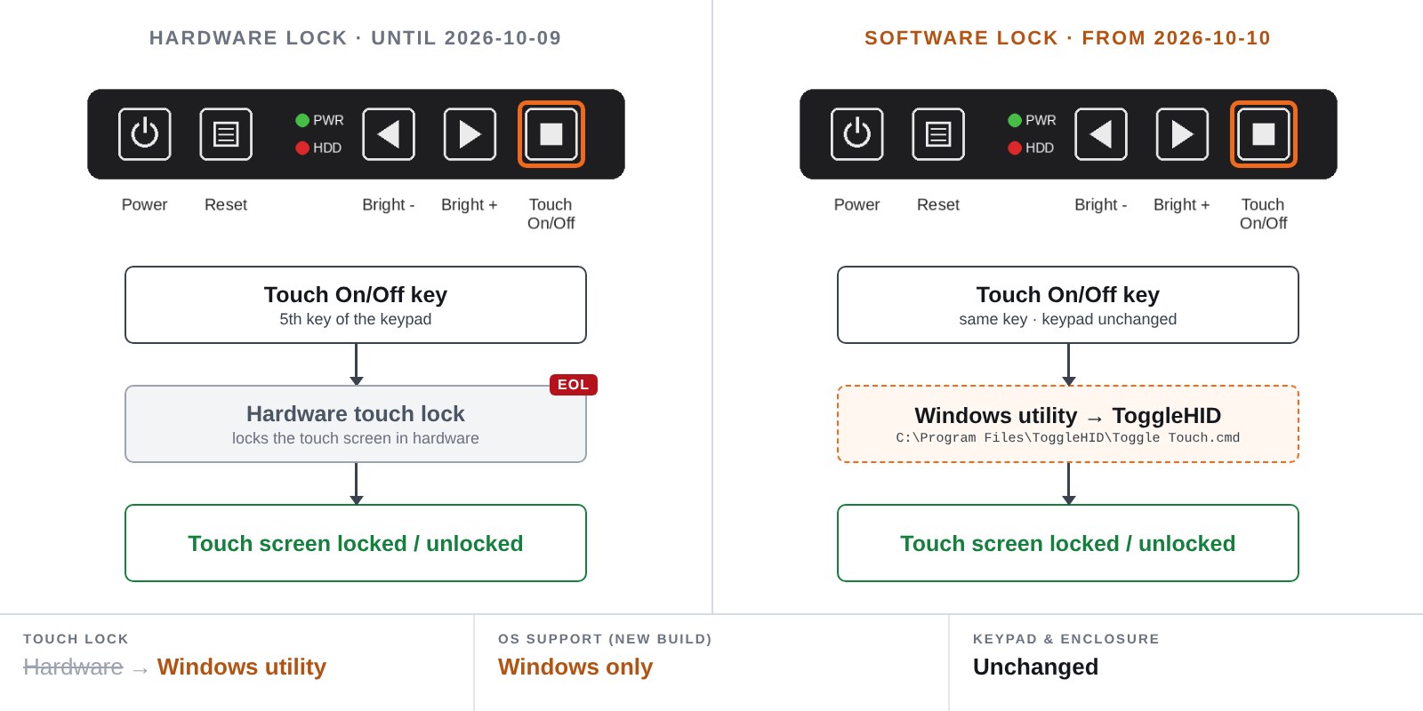
A hardware component used for the touch lock has reached end of life. On the affected panel PCs, the Touch On/Off key — the fifth key of the keypad — now locks and unlocks the touch screen through a Windows utility instead of in hardware. The keypad, the key and its function are unchanged.
BeforeAfter
What is changing
Touch lock is now done in software: pressing the Touch On/Off key runs the ToggleHID command C:\Program Files\ToggleHID\Toggle Touch.cmd, which turns the touch screen off or back on in Windows.
The Touch On/Off utility and ToggleHID are pre-installed and configured on the Windows image we ship.
The keypad, its legend and the key positions are unchanged.
Form / fit / function impact
Form / Fit — none: enclosure, keypad and key layout are unchanged. Function — under Windows the Touch On/Off key keeps the same function. Because the lock is now done in software, it only works while Windows is running with the utility installed: it has no effect before Windows has started, and it is not available under Linux or other operating systems.
Action required
Units on our factory Windows image: no action required. If you deploy your own Windows image: install the Touch On/Off utility package from the Download Center — or request it from us — then open the key-mapping utility included in the package, click Browse, select C:\Program Files\ToggleHID\Toggle Touch.cmd and click Save. Linux or other operating systems: the Touch On/Off key has no function; please contact us before ordering. Units already delivered keep the hardware touch lock and need no change.
The PPM-24WT-CP moves to the heatsink enclosure: the rear cover is 6.2 mm thicker, which increases the chassis' heat-dissipation capacity. Overall depth changes from 78.80 mm to 85.00 mm. The change is confined to the rear of the unit — the front-side dimensions on the outline drawing are identical in both versions.
What is changing
Overall depth, front face to heatsink fin tip: 78.80 mm → 85.00 mm.
Depth to the rear-cover face: 63.80 mm → 70.00 mm.
The two front-side dimensions on the outline drawing (8.00 mm and 31.80 mm) are unchanged.
The heatsink fin projection beyond the rear cover stays at 15.00 mm — the additional 6.2 mm sits entirely in the chassis body.
Form / fit / function impact
Form — overall depth grows by 6.20 mm, so 6.2 mm of additional clearance is required behind the panel. Fit — the change is at the rear of the unit only; the front-side dimensions and the heatsink fin projection are unchanged. Function — none: this is a mechanical change only, so mainboard, power input, display, touch and software image are unaffected.
Action required
Confirm that the space behind your panel or cabinet allows 6.2 mm of additional depth. Units already delivered remain at 78.80 mm and need no retrofit; both builds can be mixed in one installation. To tell them apart, measure the overall depth. The updated outline drawing and 3D model are available on request.
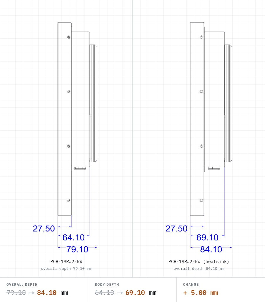
The PCH-19RJ2-5W moves to the heatsink enclosure: the rear cover is 5 mm thicker, which increases the chassis' heat-dissipation capacity. Overall depth changes from 79.10 mm to 84.10 mm. Nothing else changes — the front bezel, the display opening, the VESA pattern and the I/O panel are identical.
BeforeAfter
What is changing
Overall depth, front bezel face to heatsink fin tip: 79.10 mm → 84.10 mm.
Body depth, front bezel face to rear-cover face: 64.10 mm → 69.10 mm.
Front bezel thickness (27.50 mm) and heatsink fin projection (15.00 mm) are unchanged — the additional 5 mm sits entirely in the chassis body.
Bezel outline (466.80 × 391.50 mm), display opening (377.30 × 302.05 mm), the 8 × M4 VESA pattern and the bottom I/O panel are unchanged.
Form / fit / function impact
Form — overall depth grows by 5.00 mm. Fit — the panel cut-out and the VESA mounting interface are unchanged, so existing cut-outs and mounting plates stay valid. Function — none: mainboard, power input, display, touch and software image are unaffected.
Action required
Confirm your cabinet or enclosure has 5 mm of additional clearance behind the mounting surface. Units already delivered remain at 79.10 mm and need no retrofit; both builds can be mixed in one installation. To tell them apart, measure the overall depth. The updated outline drawing and 3D model are available on request.
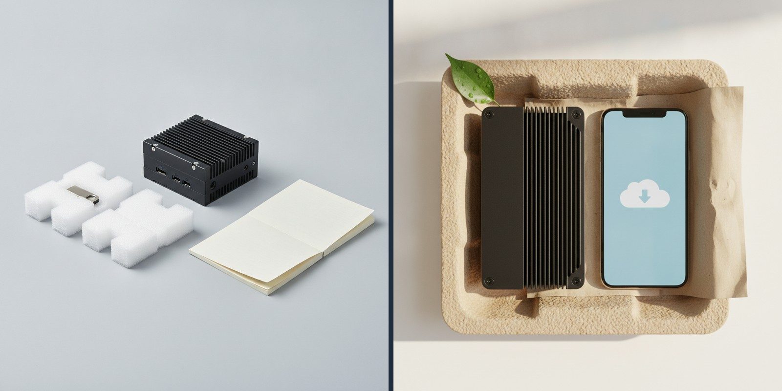
We are replacing EPE foam packaging with recyclable paper-based packaging, and moving product documentation and driver/BIOS/OS delivery fully online. There is no change to the product itself or its protection in transit.
BeforeAfter
What is changing
Protective packaging changes from EPE (expanded polyethylene) foam to moulded paper-pulp and corrugated inserts — recyclable through ordinary paper streams.
The bundled USB flash drive is discontinued. Drivers, BIOS and OS/recovery images are now obtained from the online Download Center via serial-number lookup.
The printed manual is discontinued. Manuals and datasheets are available online.
Form / fit / function impact
No form, fit or function impact. The product, its part number and its drop/vibration protection are unchanged; only packaging and documentation delivery change.
Action required
No action required. For a unit's drivers, BIOS, OS image or manual, use the Serial / Project lookup or the Download Center.
Need a signed PCN or a material declaration for your records? Contact us.
We use essential cookies to make this site work and, with your consent,
analytics cookies to understand usage and improve it. See our
Privacy & Cookies notice.